User Tools
Sidebar
Table of Contents
QO-100 Linux SDR Transceiver
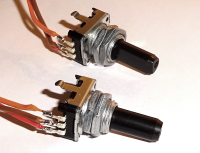
Raspberry with rotary encoder
Starting with V 1.69 the software supports the connection of 2 rotary encoders to the GPIO bar of the Raspberry PI.
Rotary encoders have two internal switches with a common pin (usually the middle one), which is wired to GND. The two outer pins output a phase-shifted square wave signal when rotated which is applied to GPIO pins on the Raspberry header.
Encoder-1: frequency setting
Encoder-2: Receive volume (in addition to the mixer)
Connection
Pictures for the 40 pin header can be easily found on the internet. The pins are connected as follows:
| pin no. | name | encoder | pin | |
| 11 | GPIO17 | Frequency | A | |
| 13 | GPIO27 | Frequency | B | |
| 7 | GPIO4 | Volume | A | |
| 15 | GPIO22 | Volume | B | |
| 9 | GND | both | center pin | |
| 1 | 3,3V | 4x pullup 2,2kOhm on A and B of both encoders | ||
so from each encoder a 3 pin cable goes to the GPIO strip of the Raspberry. Where the middle pins are connected to the common ground. You also need 4 resistors 2.2kOhm, which go from the common 3.3V (pin 1 of the connector) to all A and B connectors (please make sure that pin1 with 3.3V is really used. On the connector there are also 5V, which must not be used at all).
There are rotary encoders that additionally have a switch that is actuated by pressing. This switch can also be used and is connected like this:
| Pin No. | Name | Encoder | Function | |
| 12 | GPIO18 | Frequency | PTT | |
| 16 | GPIO23 | Volume | Mute |
both lines need a pullup resistor of about 1k to 10k against +3.3V. The switches are wired against ground.
The PTT connector can of course also be used for any external PTT button.
The mute function turns down the volume in receive mode, which is handy if you want to mute the device temporarily (e.g. during a phone call etc.).
Function
The maximum volume is automatically limited so that the audio signal is not distorted. If the volume is not enough, you can increase it further in the mixer.
The frequency setting has an “acceleration” function. If you turn very slowly, the step size is 25 Hz. If you turn fast, the step size is increased up to 5kHz. Experience shows that coarse frequency steps are easier to set with the mouse or touch screen. The rotary encoder shows its advantages in the fine adjustment.
PTT output
to control a power amplifier you need a PTT signal. Often this is generated by modifying the Pluto, but it is not everyone's cup of tea to solder in a Pluto. Therefore you can get the PTT signal on the GPIO strip of the Raspberry PI:
| Pin No. | Name | Function | |
| 18 | GPIO24 | PTT output |
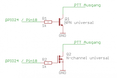
to generate the PTT signal you need a transistor or mosfet and connect it like this:
The signal at GPIO24 is normally at GND and goes to +3.3 volts when sending. If possible, the MOSFET solution is preferred as it draws less current from the Raspi. The PTT output is pulled to ground when sending, which is the function of common PTT connectors.
Practically every NPN transistor should be suitable. If a MOSFET is used, make sure that it switches at 3V gate voltage or below (see data sheet).


