Table of Contents
QO-100 Amsat-DL UPconverter with 6W PA
Assembly
Enclosed material:
- 1 pc. Circuit board UpCon6W
- 1 pc. optional thermal pad 3 mm thick (a 2mm thick thermal pad is already glued on the board at the right place)
- 2 pcs. SMA socket (one SMA socket is already soldered on the board so that a test of the board can be done after assembly)
- 1 pc. 3×2 row pin header grid 2,54 mm
- 1 pc. platinum connector 3-pole for the 12 V power supply
additionally needed material:
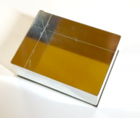
- 1 pc. Tinplate case 55 × 74 mm, 30 mm high (supplier e.g.: Otto Schubert GmbH or VHF reports)
- 1 pc. Aluminum plate or heat sink: at least 55 × 74 mm (this is the minimum dimension, which is the size of the tinplate case, but it may be any larger).
- An aluminum plate should have a thickness of at least 10 mm or more (recommended 20 mm, then no further cooling is required).
- Examples for heat sinks from the assortment at Reichelt: V7331G or SK 04/75/SA or any other, which have a smooth surface of at least 55 × 74 mm.
- Somewhat more fitting would be the Farnell No.: 170088. But you should also search your tinkering box. Since an exact measurement is not important, something suitable may already be available.
- 6 pcs. M3 screws, length 8 mm
- 6 pcs. Spacer bolts, length 3 mm, hole diameter 3 mm. The material thickness must be thin, thinner than commercial bolts. The best material is a brass tube from the model shop or hardware store with an inner diameter of 3 mm, from which you cut suitable pieces. Also suitable are plastic washers with 3 mm hole, because you can easily cut off protruding parts.
- 1 pc. Banana jack red, or 9-pin Sub-D jack, see text.
Preparation of the tinplate housing:
Insert the side parts of the tinplate housing into the covers and assemble them on a trial basis:
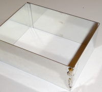
Using a hot soldering iron, solder the side panels (only the side panels, not the lid) so that a sturdy frame is formed.
Insert the circuit board on a trial basis. The frame has a small protrusion on the inside, where the tinplate parts lie lie on top of each other. Use a file to file off the PCB at these two places so that it fits well into the tinplate frame. It is not soldered, just put it in on a trial basis. Now you can take the measurements for the connector cutouts. Cut (e.g. with a Dremel) or file three slots with 10 mm height and 6 mm width.
Preparing the aluminum plate or heat sink
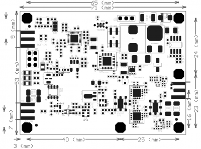
Using the hole plan, drill six 2.5 mm diameter holes (about 8 mm deep, or clearance hole) in the aluminum plate or heat sink, then cut M3 threads. A drop of oil can greatly extend the life of the tap. Figure 5 shows the dimensions of the board. Attention: these are the dimensions of the PCB. If you measure the tinplate housing, you have to add its wall thickness and gap dimensions if necessary! It is best to place the board loosely in the tinplate frame for measuring.
Preparation of the circuit board
As described above for the tinplate case, file off the corners of the PCB so that it fits into the tinplate frame.
- Mounting of 2 pieces of SMA sockets. These are pushed onto the side of the board and soldered on both sides. The 3rd SMA socket is already mounted.
- Soldering of the platinum connector for the 12 V power supply.
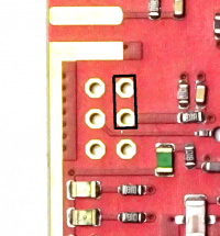
- Soldering the 2×3 row header for PTT and serial interface. On the bottom side of the board, cut the protruding pins of the pin header relatively short, so that they cannot touch the heat sink later. Normally, the PTT can stay connected to ground, you only have to put on a jumper and don't have to pay attention to the pin header.
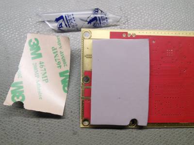
- Sticking on the heat conduction pad. At the beginning the upconverters were delivered with separately enclosed thermal pads with a thickness of a little bit more than 3mm. To stick them on, you first have to peel off the protective foil from the adhesive side and stick it on the marked spot on the bottom of the board, then also peel off the second protective foil.
- Stacking 2 thermal pads. recently the upconverters are shipped with a 2mm thermal pad already glued on. Depending on the mechanical design of the upconverter, especially its mounting on a heat sink, the 2mm gap may not be sufficient to screw an SMA connector onto the SMA socket. That's why the current kits come with a second thermal pad. So now you can set the distance to 2mm, 3mm (remove old pad and glue on new one) or 5mm (glue the 2nd pad on the first one). This gives you maximum flexibility. It is important to remove both the top and bottom protective film from all thermal pads. Otherwise, the specified thermal conductivity values will not be achieved and heat buildup will occur. If the two pads should have a different color, it does not hurt. Different manufacturers have been tested and depending on availability and price the pads will be purchased.
Mounting the board on the heat sink or aluminum plate
In these pictures an aluminum plate 57 × 78 mm and 20 mm thick was used. The UpConverter is placed on the pre-drilled holes and fixed with the spacer sleeves and M3 screws. The thermal pad is 3.15 mm thick, and the spacer sleeves are 3 mm thick. This compresses the pad by 0.15 mm and provides a good heat conductive connection. If you use the 2mm pad or a stack of 2 pads, you have to use different lengths of the spacer sleeves. It is also important that the screws are tightened evenly and that the board does not bend in the process. Otherwise damage to the SMD components may occur. These are much more sensitive in this respect compared to wired components.
Important. Do not use 3 mm washers, they might touch the tracks! Plastic washers or 3 mm sections of brass tubes are best suited. Now the tinplate frame is put on until it rests on the heat sink. Then it is soldered to the edge of the board. For the 12 V supply, you can install a banana jack, or a multi-pin connector (e.g. Sub-D 9-pin) if you also want to feed out PTT and the serial output. But this is not absolutely necessary, because in most cases you can connect the PTT with a jumper firmly to ground:
After connecting the 12 V supply line and possibly plugging jumpers for frequency selection, the lid of the tinplate housing can be put on. Finally, a label is glued on. The lid is not soldered, because you may have to make settings on the board (e.g. jumpers).
