QO-100 Amsat-DL UPconverter with 6W PA
Connectors
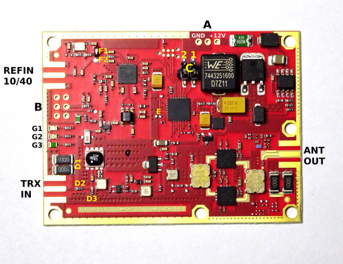
TRX IN
the transmitter (transceiver) is connected here. Maximum power 2 W, usual power up to 1 W.
ANT OUT
2.4 GHz output (max. 6 W) to the antenna (feed). Please ensure a VSWR of 1:1.5 or better.
REFIN 10/40
Input for an external (e.g. GPS stabilized) reference frequency. See also F1/F2 and E. The level on the part of AMSAT-DL DownConverter here is 1Vpp for 40 MHz, but also applies to 10 MHz. Note that the reference input is terminated with 50 ohms.
A
Connection for the 12 V supply voltage. A voltage between 9 and 15 V with a load capacity of approx. 3 A is required. For example, a common 13.8 V station supply can be used.
B
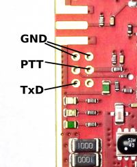
6-pin header with the following pin assignment:
- PTT input: open = receive, shorted with GND = transmit. Can normally always remain closed. If you want to save the quiescent current of the PA (about 100 mA), you can connect the connector to the PTT output of the transceiver, it is not necessary.
- TxDs erial output of plain text diagnostic data. Level 3.3 V, 9600 Bd, 8 bit, 1 stop bit, no parity. Please do not connect the other two contacts.
C
Two jumpers to select the transmit frequency of the connected transceiver (transmitter):
| transmit frequency of the trx | jumper 1 | jumper 2 |
| 430 MHz | open | open |
| 435 MHz | to | open |
| 830 MHz | open | to |
| 1290 MHz | to | to |
D
D1, D2 and D3 form an input attenuator. See “Input attenuator”.
E
Solder bridge to select reference frequency.
- open = 40 MHz, closed = 10 MHz.
- Default setting is “open”. If the internal 40 MHz TCXO is used (see jumper F1/F2), E must be open.
- E is closed only if an external 10 MHz reference is to be used.
F
Solder bridge to select internal/external reference.
- F1 closed, F2 open … the internal 40 MHz TCXO is used (this is the configuration of the module as delivered).
- F1 open, F2 closed … the reference frequency from the SMA connector REFIN is used. Depending on whether 10 or 40 MHz are fed in here, jumper E must be set. Default setting is 40 MHz, because usually the GPS stabilized 40 MHz reference supplied by the AMSAT-DL downconverter is used.
G
LEDs 1,2 and 3:
- 1 TX, red. Lights in transmit mode when PTT is enabled (see B).
- 2 SYNC, yellow. Lights up as soon as the reference oscillator is synchronized. When operating with the internal TCXO, this LED lights up immediately after power-up. In operation with external reference frequency (see F) this LED is also on. If it is not lit or flashes, the external reference is not sufficiently stable.
- 3 ALIVE, green. This LED indicates the operating status. It must always flash as soon as the board is switched on.

