User Tools
Sidebar
Table of Contents
AMSAT-DL QO-100 DownConverter V3d
Clock generation details
Clocks for transmit mixers:
Transmit mixers are required if you want to convert the transmit frequency of an amateur radio transceiver to 2.4GHz. Many commercially available transmit mixers have a 10 MHz reference input. Therefore a GPS synchronous 10 MHz signal is offered at a SMA connector and can be connected directly to the transmitter mixer. For the AMSAT-DL upconverter the 40 MHz reference signal has to be used.
Reference clock for the LNB:
The AMSAT-DL DownConverter V3d generates a 24, 25 or 26 MHz clock which is used as a stable replacement for the crystal built into the LNB. This frequency is fed into the cable to the LNB via a filter and therefore does not require a separate line.
Attention: The reference clock is only applied to the WB-LNB connector.
With two jumpers the frequency is selectable.
A usual standard LNB has a reference frequency of 25 MHz (in former times also 27 MHz). This is multiplied by 390 in the LNB, resulting in a mixed frequency of 25×390=9750 MHz.
Because of the transmission frequency of QO-100, the output signal of the LNB is at approx. 740 MHz. However, since LNBs are optimized for output frequencies of about 1-2 GHz, you may lose a few dB of signal-to-noise ratio. Furthermore, a DVB-S2 signal of 740 MHz is outside the reception range of common satellite receivers.
Therefore the frequency of 24 MHz was chosen as standard. In the DATV receiver, set IF = 9360 MHz (instead of 9750 MHz) as the mixing frequency. The wideband transponder of QO-100 is then receivable e.g. with the Octagon SF8008 satellite receiver.
The setting 26 MHz is intended for older LNBs which use a 27 MHz crystal.
The clock frequency for the LNB is coupled into one of the receive lines with a filter circuit and decoupled again within the LNB with a simple L/C combination.
Frequency stability, accuracy and jitter:
The entire downconverter board incl. attached GPS module V2 must be absolutely protected in a housing against draught, in order to minimize short time drift! In any case, an RF closed 110 x 74 x 30 mm standard Schubert tinplate case is recommended.
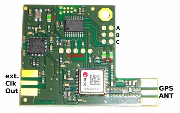
The Ublox GPS receiver has an extremely high stability but a strong jitter. Therefore an additional integrated circuit on the GPS module V2 was built in which reduces this jitter by means of a slow PLL in order to provide a clean reference. On the downconverter board such an IC is built in again so that very clean signals are available at its output.
On the GPS module V2 a SMA socket can be soldered on if necessary and an adjustable reference frequency can be coupled out. However, it is preferable in any case to use the reference frequencies from the AMSAT-DL downconverter V3d, because as described before these reference frequency outputs are double filtered and have a lower phase noise.
Feeding in an external reference:
If you already have a stable 10 MHz frequency standard (e.g. Rubidium) you can also use it as a reference. It is connected to pin-5 of the expansion connector, pin-3 and pin-4 are bridged with a jumper.
All clocks are then derived from this reference.


