User Tools
Sidebar
Table of Contents
Housing kit for up/downconverter
Overview
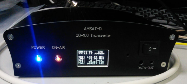
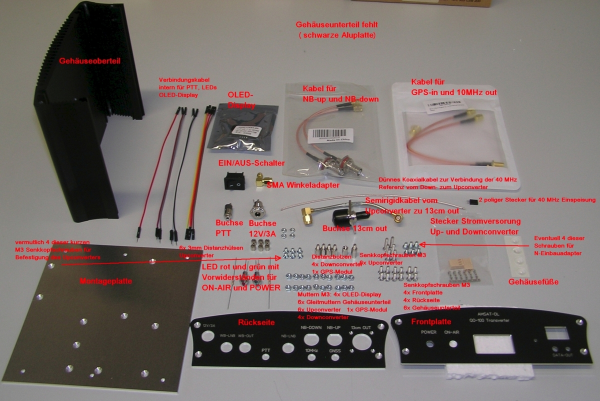
In the following a shapely housing is described, in which AMSAT-DL QO-100 Upconverter UpCon6W and Downconverter V3d can be optimally installed. The matte black anodized case is very compact with a length of 150mm and a width of 170mm. The integrated cooling fins of the extruded aluminum case provide sufficient cooling for the upconverter with the integrated 6W PA without the need for a fan. The front panel and rear panel are professionally manufactured (Figure 1). The housing kit can be purchased from the AMSAT-DL store Amsat Shop.
Figure 1: Ready built transverter in the new housing.
Explanation of the connections on front panel and rear panel:
Front panel and rear panel are already provided with all cutouts and labels.
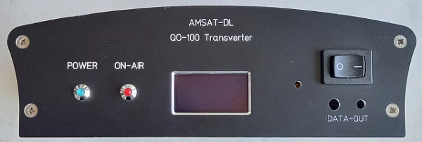
Figure 2: Layout of the front panel
The front panel (Figure 2) contains the following elements (from left to right):
- POWER LED to indicate that the device is turned on,
- ON-AIR LED to indicate that the unit is on the air,
- recess with stud for 1.3“ OLED display to indicate various operating parameters,
- rectangular recess for ON/OFF switch,
- the hole to the left allows to switch the receive IF of the downconverter with a thin screwdriver without opening the case,
- the two holes DATA-OUT below the ON/OFF switch are for 3.5mm and 2.5mm jack sockets to read out the operating data of the transverter via a serial interface. It is planned to develop a corresponding interface board and to offer it for retrofitting.
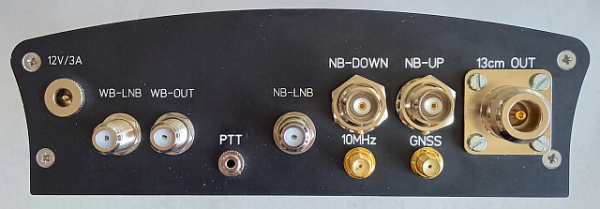
On the backside of the case there are 10 sockets in total.
Figure 3: Layout of the rear panel
It contains the following elements (Figure 3 from left to right):
- Hollow socket “12V/3A” for power supply (9-15V, max. 3A DC),
- F-socket “WB-LNB” for connection to the wideband output of the LNB. On this socket there is typically 18V to supply the LNB (can be reconfigured with jumpers) as well as a configurable GPS-stabilized reference frequency for the LNB. Even if you only want to use the NB output of the LNB, you still need to connect this jack to the LNB to provide the reference frequency for the LNB to work.
- F jack “WB-OUT” at which the looped signal WB-LNB signal for a DATV receiver can be tapped.
- 3.5mm jack socket “PTT” via which the upconverter incl. the integrated PA is activated. For this purpose the inner conductor is connected to ground. This can be done permanently or only when transmitting via a corresponding output of the transceiver. The latter saves power which is especially helpful for portable operation.
- F-socket “NB-LNB” is connected to the narrowband output of the LNB and also supplies the 14V supply voltage to this part of the LNB.
- BNC socket “NB-DOWN” supplies the receive IF output signal of the narrowband transponder. It is recommended to use a receive IF of 145MHz.
- SMA socket “10 MHz” provides a GPS synchronized 10MHz reference signal when using the AMSAT-DL downconverter (version with GPS module V2) for example to stabilize the transceiver.
- BNC socket “NB-UP” is connected to the transmitter output of the transceiver. A transmit IF of 435MHz is recommended. The power of the TRX should be 1W (max. 2W).
- SMA socket “GNSS” to connect an active GPS patch antenna. This is also supplied with 3.3V via this socket.
- N-jack “13cm OUT” supplies the 13cm transmit signal with a maximum output power of 6W. Attention never transmit without connecting an antenna or dummy load.


