User Tools
Sidebar
Table of Contents
AMSAT-DL 2.4 GHz 6W PA
Circuit diagram HF part
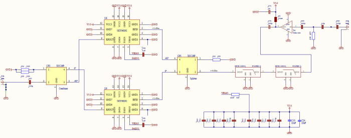
The input signal (in the circuit diagram on the right) is first adapted to the input of the driver amplifier and then
46 dB version: amplified by approx. 16dB from this MMIC of the type Minicircuits GVA-84 +.
20 dB version: attenuated by 10 dB in one attenuator. This attenuator made of SMD resistors can be changed depending on the application.
Unwanted secondary emissions, for example from a local oscillator that is not optimally suppressed in the transmitter, are then suppressed by 2 cascaded LTCC bandpass filters from Mini-Circuits of the type BFCN-2450 +.
The signal is then divided by a 90 degree hybrid coupler to 2 low-power amplifiers from Skyworks of the type SKY66292. After both partial signals have been amplified by approx. 35dB, they are combined in another identical 90 degree hybrid coupler and the sum signal is made available at the output socket (on the left in the circuit diagram). Both hybrid couplers of the type GSC356-HYB2500 from Soshin offer sufficient reserve with a nominal maximum power of 100W.


