User Tools
Sidebar
QO-100 Amsat-DL UPconverter with 6W PA
Overview
The uplink frequency for QO-100 is in the 13 cm band (2.4 GHz). Since commercially available transceivers are only available up to a maximum of the 23 cm band, an upconverter (transmit mixer) is needed to linearly convert the signal from the transceiver to the 13 cm band.
There is a large selection of upconverters, but in addition to the converter, a suitable 13-cm power amplifier is also needed to generate the required transmit power of about 5 W. These power amplifiers are usually supplied with the transceiver. These power amplifiers are usually supplied with 24 V. To make the setup of a QO-100 station as easy as possible, some functions have been combined and optimized in the AMSAT-DL upconverter UpCon6W:
- Transmitter mixer and power amplifier are located together on a board measuring only 71 × 53 mm.
- all components (including the power amplifier) are supplied with the usual 12 V (this allows portable operation without a voltage converter)
- Seamless cooperation with the AMSAT-DL downconverter, allowing GPS-stabilized operation of the complete QO-100 system.
- Mixer and amplifier optimized for SSB as well as DATV
- Input for a choice of two frequencies in the 70 cm band, 23 cm or 800 MHz (for SDR and DATV applications)
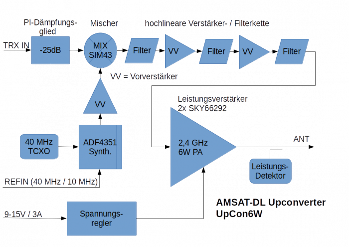
An important point is the very efficient switching regulator for generating the operating voltage for the 6 W output stage. It works with any voltage between 9 and 15 V at an efficiency of more than 90%. Requirements of portable stations have led to the selection of this circuit, since a supply of 12 V was required.
The 6-W output stage consists of two parallel SKY66292s. These, ICs built for cellular and wifi applications, provide high linearity with a gain of over 35 dB.
At full output power, the UpCon6W requires about 2 A. So a power supply should be able to deliver about 12 V/3 A. For long or thin supply lines, it is recommended to connect an electrolytic capacitor larger than 1000 mmF/25 V to minimize voltage dips due to cable resistance.
A high quality mixer from Mini-Circuits SIM-43 is used. This mixes the transmitter input signal with a local signal generated by an ADF4351. The reference can be either the internal 40 MHz TCXO (0.5 ppm) or an externally supplied reference frequency of 40 MHz or 10 MHz. Following the mixer is a chain of amplifiers and filters. Special emphasis was placed on optimum linearity in order to amplify even DATV signals with the best shoulder spacing.
Up to a symbol rate of 2 MS/s a very good linearity was measured and practically tested. Even if linearity is less critical in SSB operation, it benefits especially digital signals (e.g. digital SSTV) and reduces the error rate.


