User Tools

Site Tools


en:gpsv2:overview

GPS Module V2

Overview

There are several possibilities for clean and stable reception of QO-100, for example a stable OCXOs or the software beacon synchronization and finally the use of a GPSDO, i.e. an oscillator stabilized by GPS.

A normal crystal cannot be used for SSB reception because of the high temperature dependence. Even high quality TCXOs offer only limited stability and are not sufficient especially for very narrowband digital modes. The reason for this is the high receive frequency of about 10490 MHz.

As receiving antenna we usually use a parabolic reflector with a commercial LNB, as they are offered for TV reception. The signal in the 10 GHz / 3cm band must be mixed down to be received by common analog receivers or SDRs. This task is performed by the mixer built into each LNB. This mixer mixes the receive frequency of 10490 MHz with a reference frequency (LO, local oscillator) of 9750 MHz. The result is the received signal at 10490 - 9750 = 740 MHz where it can be easily can be processed without problems or received directly.

The LNB generates its reference of 9750 MHz by multiplying a crystal frequency of 25 MHz by the factor 390 (25 MHz * 390 = 9750 MHz).

There are also LNBs with 27 MHz and a correspondingly different multiplication factor, but the operating principle is always the same.

This multiplication is the cause of frequency drift and frequency offset in the range up to a few kHz. Here is an example:

Perfect crystal frequency results in these frequencies:

CW beacon: 10489.500 MHz
crystal frequency: 25,000 MHz
LNB-LO: 9750 MHz (crystal * 390)
Received signal: 10489,500 - 9750 = 739,500 MHz

If now the 25 MHz crystal deviates only by a tiny 1ppm (1 part per million, i.e. 0.0001%) due to e.g. temperature change, the calculation looks like this:

CW beacon: 10489,500 MHz
crystal frequency: 25,000025 MHz
LNB-LO: 9750,00975 MHz (crystal * 390)
Received signal: 10489,500 - 9750,00975 = 739,49025 MHz

This is a deviation from the nominal frequency of almost 10 kHz. For SSB or even CW operation and also all narrowband digital modes this is a dramatic error which makes QSO operation impossible.

solution to all frequency drift and stability problems is GPS:

The solution is simple: the 25 MHz crystal in the LNB must be removed and replaced by an external very stable reference frequency. Here AMSAT-DL offers an already modified matching LNB, which gets the 25 MHz from the AMSAT-DL downconverter V3 via the coaxial cable of the WB output.

From the above calculation you can easily see that the external reference really has to be very accurate and stable. The best is just good enough here.

The reference with highest stability, which can be obtained at manageable costs, are GPS synchronized frequency standards. With this, an accuracy of 5ppb (= 0.005 ppm) can be achieved. When used in the above calculation, this would correspond to a deviation of the AF signal by a maximum of 50 Hz. In fact, this deviation can also be measured on QO-100. It is especially important that the frequency jitter is extremely low and the signals are therefore clean.

Most GPS references use receiver modules from the manufacturer ublox. Some of these modules have an output with a programmable reference frequency, e.g. the MAX8Q. With a serial command this output can be programmed. In the case of the AMSAT-DL GPS module V2, this is done on an output frequency of 10 MHz.

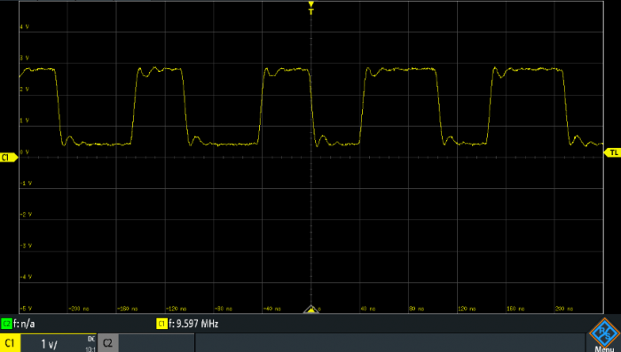
However, the MAX8Q does not contain an internal PLL. The output frequency is generated by truncating individual periods from an internal crystal frequency to produce, on average, the desired output frequency. This method is very accurate (5ppb) but has extreme jitter, as can be seen in the following oscillogram:

10 MHz output signal of the MAX8Q

As can be seen in the oscillogram above, the output waveform is not a 10 MHz sinusoidal signal, but the rectangular output signal has different period lengths. In fact, it jumps back and forth around 10 MHz quite wildly, but on time average, the fundamental has a precise frequency of 10 MHz.

Removing the jitter:

Before the reference frequency of the GPS module can be used to stabilize the LNB or for the PLL of the downconverter, the jitter must be removed. In the past, slow analog PLLs would have been built by oneself. Today, there are special integrated circuits (ICs) that offer ready-made solutions. These originate from network technology, since clocks with extremely small jitter are also required in gigabit networks.

However, many things are not quite as simple as they first appear. In tests of various “jitter attenuator” circuits, Silicon Labs' ICs have proven themselves. The circuit with the slowest PLL loop is the si5328, and the loop must be very slow indeed to sufficiently reduce the jitter of the ublox MAX8Q.

Since other GPS references also use this operating principle, detailed measurements could be made in advance to investigate known problems: some OMs had a strange, similar to RTTY sounding noise on the received signal after connecting a GPS reference to the LNB, best audible at the CW beacon. Further problems appeared with DATV receivers. When using an external GPS reference, the MER value of received signals became worse and the error rate increased.

Shortly after QO-100 was put into operation, a possible solution was published on the Internet. The GPS reference frequency is programmed “wrong” by a small amount. Instead of 25 MHz one sets for example 25,000004 MHz, thus e.g. 4 Hz too much. The exact value has to be determined experimentally until the signals are clean. Sometimes you are lucky and don't need an offset, it depends on the exact frequencies of the built-in TCXOs.

This trick works, but then the frequencies are shifted. Due to the multiplication in the LNB by a factor of 390, one has to live with a resulting offset of several 100 Hz.

We did not want to accept this emergency solution during the development of the AMSAT-DL GPS Module V2. Therefore we analyzed the problem in countless series of measurements and finally found an improved solution:

Three independent clock sources are involved in the frequency generation:

1. the GPS reference which is generated in the ublox module from the received signal
2. the TCXO inside the soldered ublox GPS module,\ 3. the TCXO on the AMSAT-DL GPS module V2 for the jitter attenuator circuit.

What is not a problem with analog PLLs, however, may lead to unclean signals with digital asynchronous solutions. Especially at frequencies that are in an integer ratio to each other, these clocks can produce mixed products (best described as beat). This is a result of the digital dividers and multipliers with their finite number of digits. The closer the bars (or integer parts or multiples) are to each other, the stronger these unwanted mixing products become. This also explains why the trick with a slight frequency offset works. This brings the beats into a higher frequency range where they can be removed more easily by the PLL.

In the AMSAT-DL GPS module V2 circuit parts are built in to get always a stable signal with lowest jitter even at arbitrary frequencies.

The DATV reception could be improved by choosing other VCO frequencies. This eliminates the part of the jitter which could influence the MER.

For SSB operation especially the low frequency jitter is very disturbing. Since a si5328 jitter attenuator has only a finite jitter attenuation due to its built-in loop bandwidth (which is often insufficient), this PLL was also enhanced with additional circuitry and also removed the remaining jitter by special programming.

The result is a clean reference signal which is still extremely stable despite multiplication by 390. This function is given when the GPS module V2 is operated on the AMSAT-DL downconverter V3, since its circuitry takes care of part of the jitter suppression. Thanks to the solution of the jitter problem, all frequencies in a QO-100 system can now be tuned with GPS accuracy.

Some transceivers (e.g. IC-9700) have external reference inputs which should also be connected so that the whole receiver path is GPS stabilized.

en/gpsv2/overview.txt · Last modified: 2021/08/27 01:09 by dj0abr